The Allen Telescope Array (ATA) is located at the Hat Creek Observatory in the Cascade Mountains of California, approximately 300 miles to the north of San Francisco and two dozen miles north of Lassen Peak. It comprises an array of 42 antennas, each 6 meters in diameter, which can be simultaneously used for both SETI and cutting-edge radio astronomy research.
The ATA is currently being upgraded with more sensitive receivers. While it is not the world’s largest antenna array, it has the advantage of being able to examine large swaths of the sky, and over a wide range of frequencies from approximately 1 – 14 GHz. Unlike other instruments that are mostly used for radio astronomy projects, the ATA can devote large amounts of time to SETI searches.
What has the Allen Telescope Array observed?
There have been several observing projects on the Allen Telescope Array. One was a reconnaissance of star systems found to have planets (or planet candidates) by NASA’s Kepler Mission, and especially those planets in the so-called habitable zone. Kepler has uncovered thousands of candidate planets since its launch, and those worlds make routine appearances on the observing lists for the ATA.
In addition, the ATA has observed a small region in the vicinity of the Milky Way’s galactic center. This is the region of highest stellar density in the galaxy, and it’s conceivable that truly advanced societies might place a “beacon” there.
A third effort by the ATA has been to observe nearby, so-called “hab stars”. These are stellar systems less than 1,000 light-years distant that have characteristics that would make them suitable hosts (“habitable”) for planets with life. This last project was an extension of Project Phoenix, a SETI Institute effort that ran from 1995 – 2004, and used radio telescopes in Australia, West Virginia, and Puerto Rico to scrutinize one thousand nearby star systems in a hunt for radio signals.
Other ATA projects have included an effort to detect any radio signals coming from the object ‘Oumuamua, and from the direction of the WOW signal, uncovered in 1977 by the (now defunct) “Big Ear” radio telescope of Ohio State University.
In 2020, new improved receivers to garner both better sensitivity and a wider frequency range for the ATA have been under construction. Several new SETI observing programs to take advantage of this new hardware are now being formulated.
Visit the Hat Creek Radio Observatory!
Home of the Allen Telescope Array
I. Introduction
The completed Allen Telescope Array (ATA) is intended to consist of approximately 350 6.1 meter offset Gregorian dishes at the Hat Creek Radio Observatory site in northern California. Given the number of antennas and a very wide field-of-view (2.45° at 21cm wavelength), this array will have an unprecedented amount of flexibility in observing. Several individual users may simultaneously use the array to observe a different part of the sky at an independent frequency, or image the sky at one or more frequencies.
II. Overall Architecture
The ATA has four main conceptual systems:
(1) the antenna collects the radiation from space;
(2) the signal path brings the radiation from the feed (which is located at the antenna focus) back to the user;
(3) the monitor and command systems allow the dishes to be accurately moved, and the signal path controlled. It also monitors the health and status of the array and all of its components;
(4) the site includes the overall antenna configuration, as well as other infrastructure. The ATA will permit remote users to access and use the instrument via a secure Internet connection.
Physically, the ATA consists of many elements (350 when fully built out), which are composed of an antenna and all of the associated mechanical and electrical systems to create the signal path and to monitor and command the array. This build-out number of antennas yields approximately one hectare (10,000 m2) of geometric collecting area. Each element has a pair of analog radio frequency (RF) modulated fiber optic cables for the signal path and additional digital fiber for the monitor and command back to the converter room. The monitor and command fiber is routed directly to the control room, while the analog fiber is processed in the converter and processor rooms before ultimately getting to the user either in the control room or elsewhere via a secure Internet link. In addition, there is an antenna assembly tent for the actual fabrication, and eventually plans for the Myhrvold Development Laboratory, and a visitor's center.
Note that the elements are units highly integrated in the physical structure of the antenna. All of the major components are present at each element. The appearance of the ATA will be dominated by the large number of such elements.
III. Antenna
The ATA antenna is a 6.1-meter (approximately 20 foot) offset Gregorian antenna, with a 2.4-meter (8 foot) secondary. These reflecting elements were hydroformed from aluminum in a proprietary process under a contract with Andersen Manufacturing, in Idaho Falls, ID. A metal shroud connects the bottom half of the sub-reflector to the bottom of the primary to deflect ground spillover. The inclusion of the shroud is important in achieving lower system temperatures.
IV. Signal Path
Each of the up-to-four independent tunings is further split into four synthesized beams, which may be steered independently to different parts of the sky. The outputs are sent to either a correlator (which takes all of the signals and makes an image) or one of several phased-array back-ends (PABE’s), or SETI detectors.

V. Monitor and Command
VI. Conclusion
The Allen Telescope Array is the first implementation of a large-N, small-D radio telescope. It is a promising candidate for at least a portion of the Square Kilometer Array (SKA).
The ATA is a scalable architecture. It began operation in October 2007 with 42 elements. The rapid increase in computing capability (Moore’s Law) will drive ever-increasing functionality and performance in the digital hardware as the array is built out.
A parabolic antenna brings radio waves from a particular direction in space (along the axis of the parabola) to a focus as in Figure 1. The radio waves from the direction along the axis arrive at the focus “in phase,” i.e., they have all traveled exactly the same distance. The radio waves are collected at the focus by a “feed” antenna where they are converted to electrical signals and amplified. These signals are then sent to other electronics for further processing.
A dish antenna is most sensitive to radio waves from a narrow range of directions near its axis. This angular region of sensitivity, corresponding to a small spot on the sky, is called the antenna’s beam. The width of the beam depends on the diameter of the antenna and the wavelength of the radio waves observed. The beam width (in radians) is roughly the wavelength of the radio wave divided by the diameter of the antenna. For example, a 100 meter antenna observing at a wavelength of 21 centimeters (a frequency of 1420 MHz) has a beam width of 0.0025 radians or 0.14 degrees (about one third the angular size of the Moon).
The ATA is an array of many small dishes that can be combined to form the equivalent of a single large dish antenna. How this works is illustrated in the following diagrams based on originals by Dr. Ron Ekers.
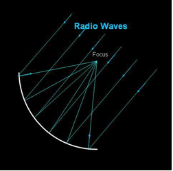
Figure 1
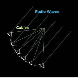
Figure 2
We can replace the solid surface of a large dish by a set of small dishes positioned along the parabolic surface as in Figure 2. Each small dish brings radio waves to a focus and converts them to electrical signals. These signals then travel by cables to the focus of the large dish. This replicates the effect of the large single dish. The cables simply replicate the path that the reflected radio waves would have taken in Figure 1.
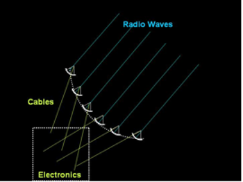
But there is no reason to send the cables up to the original focus position. As long as the lengths of the cables remain the same, they can instead go down to the ground and be collected by electronics there, as in Figure 3.

There is also no reason to suspend the small dishes above the ground. As long as we know where they would have been on the surface of the original large dish, we can put them on the ground and add an appropriate amount of cable to delay the signals as shown in Figure 4. The dish that is closest to the original position (the dotted line) will need the most delay. Combining the signals collected by the individual dishes with the appropriate delays synthesizes the effect of the large single dish, resulting in a synthesized beam equivalent to that of the large dish.
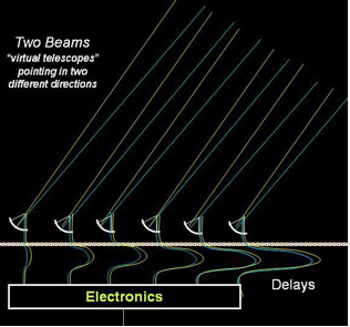
This arrangement of small dishes is called a phased array since the cables and electronics ensure that the radio waves from a particular direction are “in phase.” By carefully changing the lengths of the cables and tweaking the electronics, we could bring radio waves from a different direction into phase. In other words, we could steer the phased array without moving the dishes. If we replicate the electronics and cables, we can point in two directions at the same time as shown in Figure 5.
In practice, we use one set of cables with separate sets of electronics to change the relative delays between the dishes, and thereby synthesize multiple beams. The synthesized beams may be steered anywhere on the sky, but we usually limit them to an area corresponding to the beam width of an individual dish. (The sensitivity of the synthesized beam decreases dramatically outside of this area.) This area is called the field of view (FOV) of the array. For the ATA, with 6.1 meter dishes, the FOV at a wavelength of 21 cm is 0.04 radians or 2.5 degrees (five times the angular width of the Moon).
SETI observations use three beams to observe three stars (or positions on a sky survey grid) at the same frequency at the same time in order to eliminate signals caused by terrestrial interference. If a signal appears in two or more beams, it is almost certainly from our own equipment or from manmade interference. If a signal appears in only one beam, it is worthy of further scrutiny.
ATA Memo series

Jun 11, 2025
SETI Institute Names First William J. Welch Postdoctoral Fellow
#Press Releases #ATA #Fellowships #SETI #Hat Creek Radio Observatory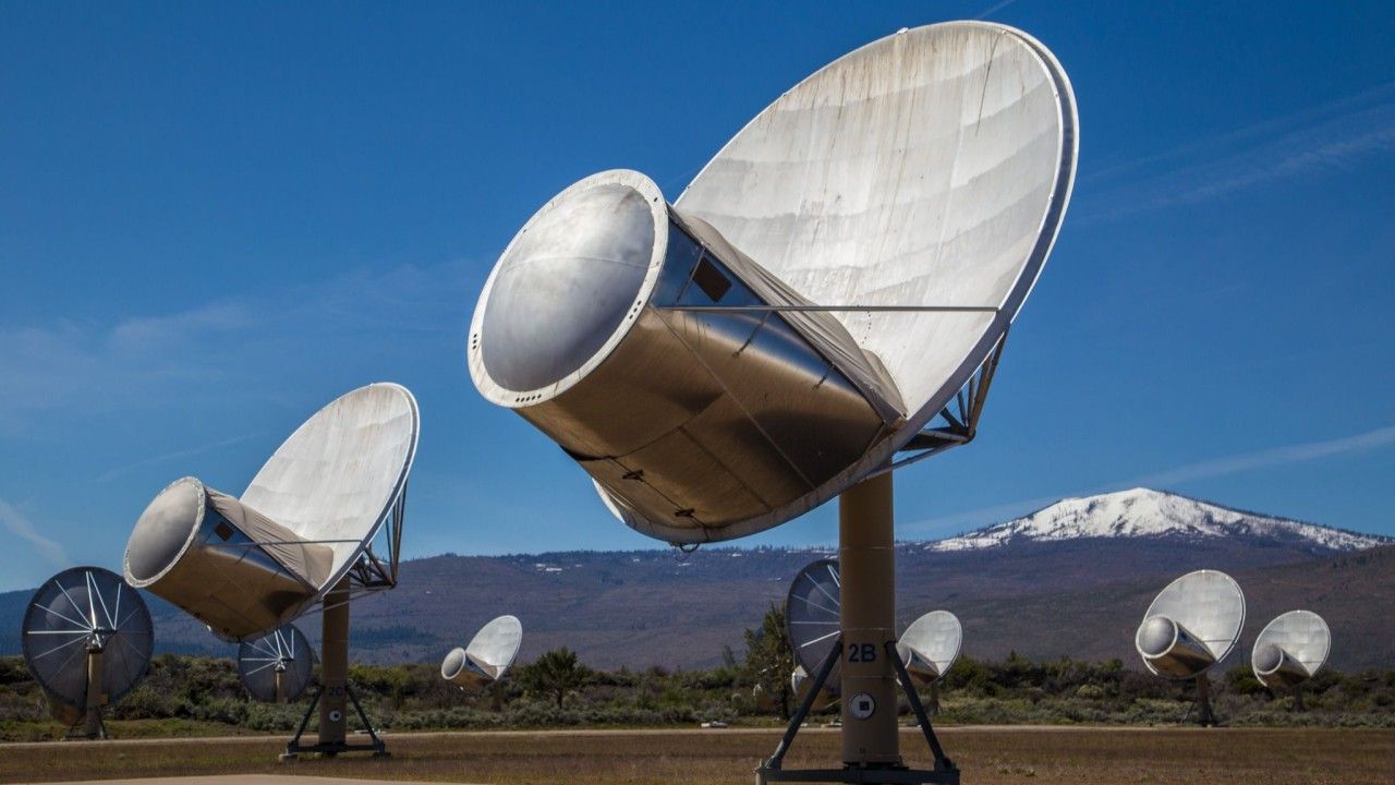
Jun 3, 2025
Signal and Image Processing Foundations of Radio Interferometry
#ATA News #SETI #ATA
Oct 16, 2024
Scientists Use Allen Telescope Array to Search for Radio Signals in the TRAPPIST-1 Star System
#Press Releases #ATA News #Trappist-1
Jun 11, 2025
#Press Releases
#ATA
#Fellowships
#SETI
#Hat Creek Radio Observatory
Jun 3, 2025
#ATA News
#SETI
#ATA
Signal and Image Processing Foundations of Radio Interferometry
Oct 16, 2024
#Press Releases
#ATA News
#Trappist-1